When expanding production capacity or upgrading industrial facilities, upgrading material handling systems to a 100-ton capacity overhead crane is frequently required. However, older or pre-existing plants are bound by fixed structural envelopes. Raising the roof of an active manufacturing bay or turbine hall is rarely economically or operationally viable due to building downtime, structural engineering complexities, and prohibitive capital expenditure.
The engineering challenge therefore falls on the 100 ton overhead crane design: maximizing hook lift height within a severely restricted vertical space. This article analyzes the technical strategies, mechanical modifications, and structural solutions required to integrate a 100-ton top-running double-girder crane into tight headroom environments.
1. Defining the Vertical Envelope Constraints
Before executing any design modifications, the physical limitations of the bay must be surveyed with high-precision 3D laser scanning. The vertical envelope is defined by four critical interfaces:
- Upper Structural Obstruction Line (H-ceil): The lowest point of the building’s roof trusses, purlins, lighting fixtures, piping, or HVAC ductwork.
- Runway Rail Elevation (H-rail): The top surface of the crane runway rail, which dictates the boundary between the upper crane structure and the lower load-carrying space.
- High Hook Elevation (H-hook): The minimum height to which the crane hook must rise to clear the tallest machine, container, or assembly jig on the production floor.
- Floor Elevation (H-floor): The baseline ground level, defining the total required lift distance: L-lift = H-hook – H-floor
Under standard industry specifications, such as the Crane Manufacturers Association of America (CMAA) Specification No. 70, a minimum mechanical clearance of 3 inches (76.2 mm) must be maintained between the highest projection of the crane (usually the top of the hoist trolley or the maintenance platform) and any overhead obstruction.
2. Mechanical Interventions for Trolley and Hoist Profiles
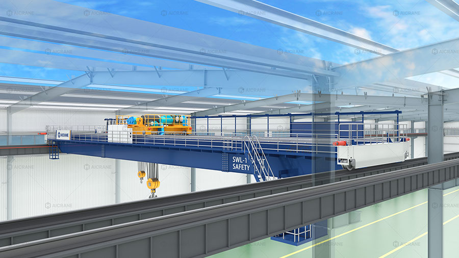
On a standard 100-ton top-running double girder overhead crane, the hoist and trolley frame sit completely on top of the crane girders. This configuration can easily require a vertical clearance of 1.8 to 2.5 meters above the runway rail. To minimize this profile, three primary mechanical re-engineering strategies are deployed.
Nested (Low-Profile) Trolley Design
Instead of running the hoist trolley wheels on top of the main bridge girders, a nested or “sunken” trolley design is utilized.
- Mechanism: The trolley frame is lowered between the two main girders. The trolley rails are mounted on the lower inside flanges of the girders, or the girder web is reinforced to support a shelf-mounted rail system.
- Impact: This approach allows the hoist drum, motor, and gearbox to sit partially or fully between the main girders rather than above them. This configuration can reduce the necessary clearance above the runway rail by up to 35% to 50%.
Custom Dropped Girder-to-End-Truck Connections
In standard 100 ton top running crane configurations, the main bridge girders rest directly on top of the end trucks (top-running connection). For low-headroom applications, this interface is redesigned.
- Flush Side-Connection: The main girders are notched or bolted flush to the side of the end trucks. This lowers the entire girder structure relative to the wheels and runway rail.
- Underhung Girder Connection: In extreme cases, the girders are suspended below the end trucks, though this requires careful structural analysis of the connection bolts under heavy dynamic shear forces.
- Result: By lowering the main girders relative to the runway rail, the overall height of the crane bridge is reduced without sacrificing the structural depth of the girders needed to limit deflection.
Optimized Reeving and Compact Hook Blocks
The vertical space occupied by the hook block and the upper sheave nest represents “dead space” where the hook cannot lift. For a 100-ton load, high-strength compacted wire ropes are used to optimize this dimension.
- Reeving Configuration: Utilizing a 12/2 or 16/2 reeving configuration distributes the load over more falls of wire rope, allowing for smaller individual rope diameters.
- Sheave Diameter (D/d Ratio): While standards like ASME B30.2 mandate strict minimum ratios for drum and sheave diameters relative to rope diameter (typically D/d >= 24 or D/d >= 30 for heavy service), using modern, high-tensile wire ropes allows the absolute sheave diameter to be kept as compact as code permits.
- Integrated Hook Blocks: The hook block can be designed with a “short-shank” hook, and the sheave nest can be partially integrated into the trolley frame structure, shortening the distance between the center of the drum and the hook saddle when the hoist is fully raised.
3. Structural and Deflection Calculations
Reducing the physical height of a 100-ton crane girder cannot come at the expense of structural rigidity. Under CMAA Class D or E service, the maximum allowable vertical deflection (Delta) under rated load plus trolley weight is limited by:
Allowable Deflection = L / 1000
Where L is the span of the crane bridge in millimeters.
To maintain this stiffness with reduced girder depth (headroom), the cross-section of the box girders must be optimized:
- Increasing Web Thickness and Width: To offset the loss of vertical depth, the width of the box girder is increased, and internal diaphragm plate configurations are redesigned to prevent web buckling.
- High-Strength Steel Alloys: Specifying ASTM A572 Grade 50 steel instead of standard ASTM A36 increases the yield strength from 36,000 psi to 50,000 psi (250 MPa to 345 MPa), allowing for thinner plate designs with equivalent capacity, thereby reducing deadweight.
4. Electrification and Accessory Space Management
Auxiliary systems such as power distribution and maintenance platforms frequently cause clearance conflicts in tight spaces.
C-Track Festoon Replacement
Traditional wire rope or C-track festoon systems carry power and control cables to the trolley via hanging loops. For a 100-ton crane, these cable loops can hang down 0.8 to 1.5 meters, creating a risk of snagging on machinery below or requiring extra vertical clearance.
- Solution: Replace festoon systems with enclosed plastic or steel cable tracks (energy chains) mounted flat on top of one of the main bridge girders. These systems lie horizontally and require less than 250 mm of vertical clearance.
Low-Profile Busbars
For main runway power delivery, open-conductor wire systems are replaced with compact, multi-pole enclosed conductor bars mounted directly to the web of the runway runway girder, eliminating overhead power collector arms.
5. Engineering Comparison: Standard vs. Low-Headroom Design
The table below outlines a comparison of a typical 100-ton crane configuration versus an engineered low-headroom configuration for a facility with a 20-meter span.
| Parameter | Standard Configuration | Low-Headroom Configuration | Space Saved |
|---|---|---|---|
| Trolley Elevation Above Rail | 2,100 mm | 1,250 mm (Nested Design) | 850 mm |
| Girder Connection Type | Top-running on End Truck | Flush Side-Connection | 350 mm |
| Hook Block Dead Space | 1,100 mm | 750 mm (Compact Block) | 350 mm |
| Power Electrification | Cable Festoon Loops | Horizontal Energy Chain | 600 mm |
| Total Headroom Saved | — | — | 2,150 mm |
6. Safety Systems and Operational Considerations
Operating a high-capacity heavy duty overhead crane in tight clearance spaces increases the risk of collision with structural components. The following safety integrations are required:
- Dual-Channel Limit Switches: Rotary limit switches are backed up by non-contact photoelectric or laser distance sensors. These sensors automatically slow the hoist or travel motions before reaching physical limits.
- Anti-Sway Control Technology: In tight spaces, lateral load sway can cause a 100-ton load or the hook block to strike columns or machinery. Variable Frequency Drives (VFDs) running proprietary electronic anti-sway algorithms must be implemented to automatically counteract pendular motion during acceleration and deceleration.
- Laser Collision Avoidance: If multiple cranes share the runway or if roof structural elements protrude at specific intervals, dual-laser collision avoidance systems are installed to program “keep-out” zones in the crane’s PLC.
7. Conclusion
Fitting a 100-ton overhead crane into an existing low-headroom facility requires a comprehensive redesign of the crane’s mechanical and structural geometry. By implementing a nested trolley frame, custom end-truck connections, compact sheave reeving, and horizontal energy chains, engineers can reclaim up to two meters of vertical operating envelope. This approach ensures that facility upgrades can proceed without the extensive structural and financial costs associated with raising the building’s roof line.